|
|
|
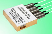
| Optical DQPSK demodulator converts quadratural phase modulation into amplitude modulation over the entire C+L band in support of data transmission rate of 10 or 40 Gb/s. DQPSK demodulator is designed for the next generation optical communications systems utilized in commercial, defense and space exploration markets. The device plays a key role in improving signal quality and performance to meet the expanding demand for higher data rates and more complex transmission formats within current and next generation systems without major capital expenditure. | | |
| |
Features and Benefits of DQPSK Demodulator:
- Athermal design
- C+L band coverage by a single device
- Low temperature-dependent frequency shift (TDFS)
- Low polarization-dependent frequency shift (PDFS)
- Wide bandwidth
- Low insertion loss & PDL
- High power handling
- Passive, semi-tunable and fully tunable operation
- Suitable for both RZ and NRZ modulation format
- Telcordia GR-1221 qualified
|
|
| |
Applications of DQPSK Demodulator:
- 5 or 20 Gb/s DQPSK Signal Reception
- Data Rate Optimization
- Extend Transmission Distances
|
|
| |
Standard Specifications of DQPSK Demodulator:
| Parameter |
Unit |
Specification |
| Wavelength Range (C-Band) |
nm |
1527 to 1567 |
| Wavelength Range (L-Band) |
nm |
1567 to 1607 |
| Free Spectral Range1 (FSR, ~1/2 of the nominal data rate, a few typical values are given) |
GHz |
10.7, 21.5, 28 or 32.5 |
| FSR Error2 |
% |
< 1 |
| Insertion Loss2 (including all connectors) |
dB |
5.7 Typical; 6.0 Max |
| Extinction Ratio2 |
dB |
> 18 |
| PMD2 |
ps |
< 0.1 |
| Return Loss |
dB |
> 40 |
| PDL2 |
dB |
< 0.2 |
| PDFS2 |
deg |
< 3 |
|
Optical Path Delay2 (Skew, among Input -> I1, I2, Q1, Q2) |
ps |
< 1.0 |
| Tuning Range |
FSR |
> 1.5 |
| Tuning Time Constant3 |
sec |
< 1.0 |
| Power Consumption |
W |
1.0 Typical; 2.0 Max |
| Tuning Voltage |
V |
0 to 5 |
| Maximum Input Optical Power |
mW |
300 |
| Operating Temperature |
°C |
-5 to 65 |
| Storage Temperature |
°C |
-40 to 85 |
| Dimension (L x W x H)4 |
mm |
50x41x11 |
| Connector Type |
- |
TBD |
| Fiber Pigtail Type |
- |
SMF-28 with 900 µm loose tube |
| Fiber pigtail length |
m |
1.0 ± 0.1 |
Notes:
1. Values listed are typical examples, customer can specify.
2. Over the stated spectral and operating temperature ranges and all polarization states.
3. Defined as the time required to reach half-way from the starting and ending points.
4. Not including five collimator sleeves extending from one longer side by 21 mm.
| |
|